[精华]罗宾逊直升机R22 Preflight(二)2016-06-08 09:10:02
简述 || 宣传航空文化,我们是认真的!在路上,因为共同的爱好而走到一起,因为相互的支持而走的更久远,从点滴做起,用实际行动把飞行的文化传播给更多的朋友,共筑中国梦,航空梦。
Engine Rear
Engine Rear
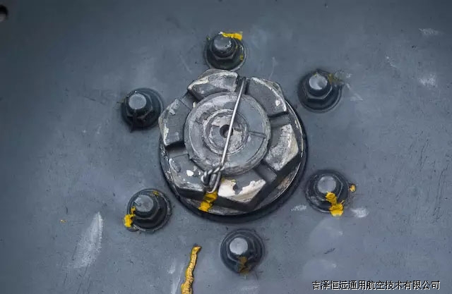
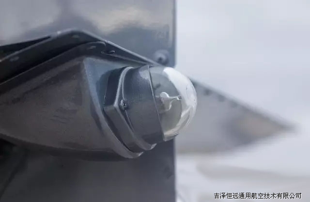
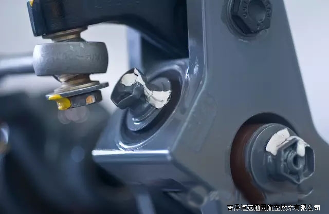
Cooling Fan Nut: Pin in line with marks
The shaft we are looking at here is where the propeller would mount when the engine is installed in an airplane. The shaft is not keyed, i.e. there is nothing to prevent the fan from spinning on the shaft except for the tension of the big nut. If the nut was to back off some, the fan could slip on the shaft. To be able to tell that this is not happening, the mechanic should put a paint mark of some kind (in this case it is yellow torque stripe) on the fan aligned with the pin and safety wire. If the pin and the paint are not lined up, this would be an indication that the fan has slipped. You should make sure that the pin and the safety wire are present, and lined up with the paint line.
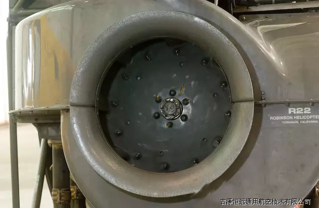
Cooling Fan: No cracks
The areas of the metal squirrel cage fan to check are around the center nut/shaft, around each of the nuts/bolts that surround the shaft, each of the nuts/bots out near the fan blades, and the welds of the blades themselves.
Fan Scroll: No cracks
The fiberglass fan scroll should be examined for cracks. It is common to see small surface crazing in the surface, but I think you should only be concerned with deep cracks that seem to extend all the way through the material.
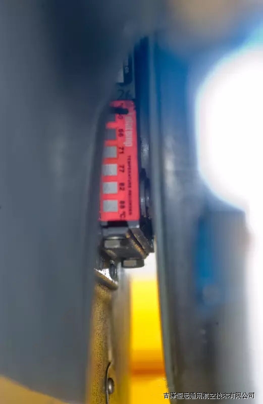
Teletemps - Lower Bearing: Normal
You can refer to a previous discussion of teletemps with respect to the main transmission. In this picture, you can see that two of the squares have turned black, indicating that the temperature has peaked at just below 71 degrees C. This is probably a normal operating temperature for this part. The pilot should keep track of which boxes were black. If on a subsequent preflight you suddenly notice that a couple more boxes have turned black, that is an indication that the part is suddenly running hotter, and you would want to look into why this is occurring.
Lower Bearing: No leaks
I find the lower bearing a difficult part to describe a preflight procedure. Early on, the R22 experienced lots of lower bearing problems, but the word at the time was that the bearing would start to push grease well before it would fail. Robinson changed the design of the lower bearing, and the word was that the pushing of grease was no longer a reliable indicator.
At the factory school, they warn you that the teletemp won't start to turn dark until the part is already into failure, so it is not a reliable indication that the part will not fail during the next flight. Some people will tell you to open the pilot door and listen to the noise it makes so that you will be aware of a different sound that the bearing may make before failure. Other people at the factory will tell you that you won't hear a difference unless you are standing right next to the part. Most of us operate in a single pilot mode where we can't be starting the helicopter and standing next to the bearing at the same time.
Personally, I just check that the teletemp looks normal, and that I'm not seeing an excessive amount of grease coming off the bearing.
Empennage
Empennage
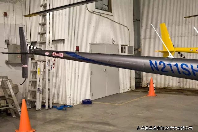
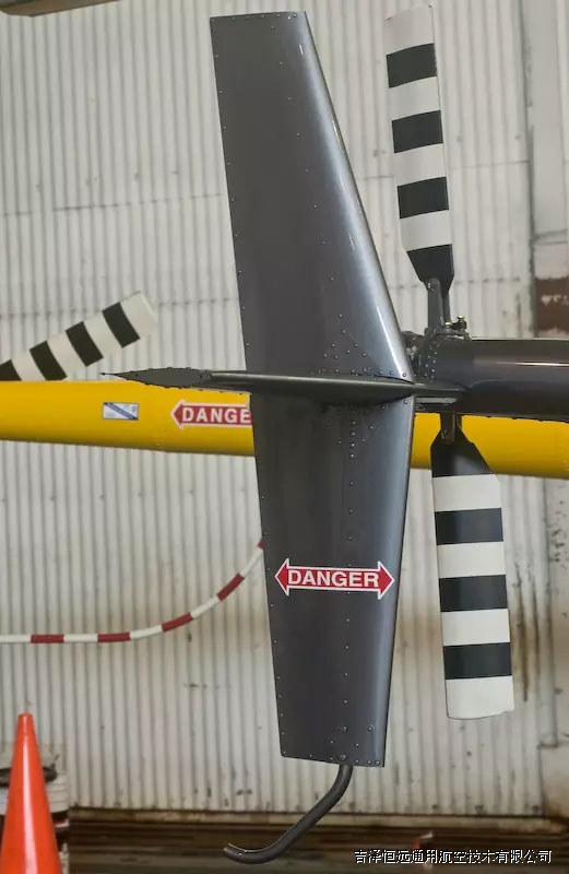
Tail Surfaces: No cracks
Check the major tail surfaces for cracks and dents. Check that the stinger hasn't been bent.
In the above picture, you can see four bolts. Each top bolt is connected to the corresponding bottom bolt with an aluminum strap. Look in the gap to see that they look normal. Give the top and the bottom fin a gentle shake to make sure that they seem firmly attached.
If you look at the corner of the skin to the left of the position light, you will often see it bent down from the way people ground handle the helicopter. You should not be pushing down on the skin to the rear of the tail surface, because it is extremely thin at this point. If you have to push down, it is better to push down using the gearbox, tail-cone, or the forward section of the tail surface where you can see the doubler riveted on.
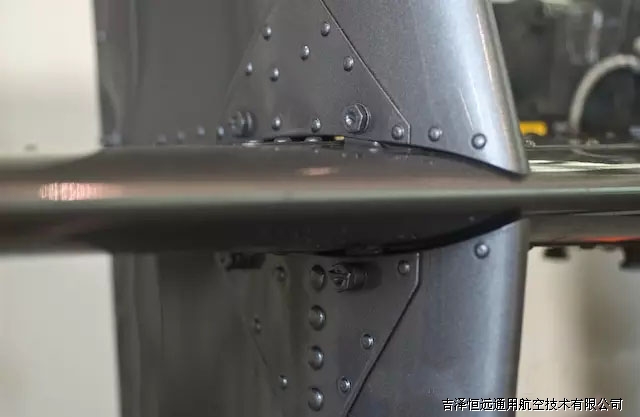
Fasteners: Tight
All the tie wraps in this picture are designed to prevent wires from interfering with the tail rotor control. Check them to be sure they are all intact.
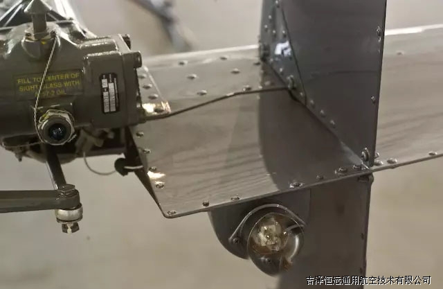
Position Light: Check
Check that the position light is attached by gently grabbing it in your hand and give it a little wiggle. It is rubber mounted so it will move slightly, but you want to make sure that it feels secure. If you are going night flying, you should turn on the master, turn on the Nav Lights, and check that the position lights (all 3) illuminate.
Tail Rotor
Tail Rotor
Gearbox Teletemp: Normal
The tail rotor gearbox teletemp is positioned as in the photograph above. It's common to see discoloration of the upper temperature boxes, I assume from the exposure to UV light from the sun.
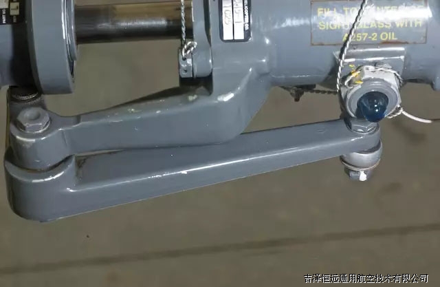
Gearbox: Oil Visible, No leaks
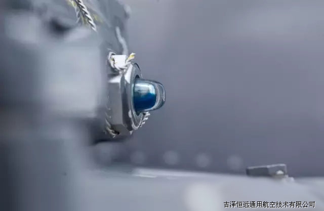
To check the tail rotor gearbox oil level, stand to the side and look sideways at the sight glass. You can see that the oil is blue, and you can see that the sight glass is about half full.
In cold climates, you should check this before you turn the rotor system, because otherwise the oil will collect on the gears and the sight glass will appear empty. When it is cold outside and the oil is thick, it can take many minutes before the oil drains off the gears and appears in the sight glass again.
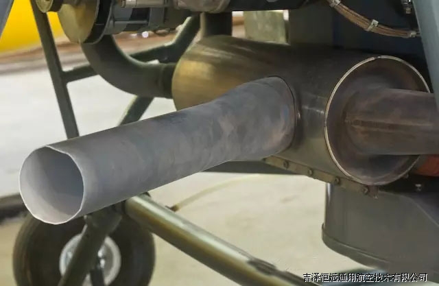
Blades: Clean and no damage/cracks
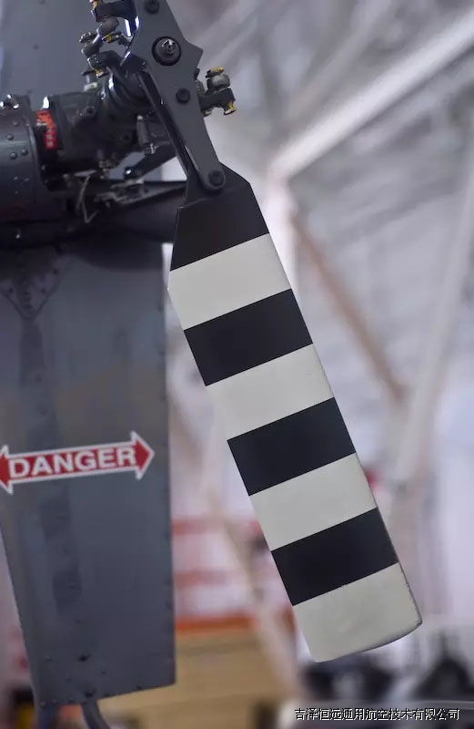
The blades themselves are just aluminum skins wrapped over on top of themselves and bonded. If you look carefully near the tip, on the right hand edge (leading edge) you can see where the paint has been worn off by dust/salt/etc/ in the air. You should check that this erosion has not actually penetrated the surface of the blade - if so the blade needs to be replaced.
Check for any indication on the tip caps that the blade may have hit the ground or other objects. Look at the blade from several directions and make sure it has not been bent.
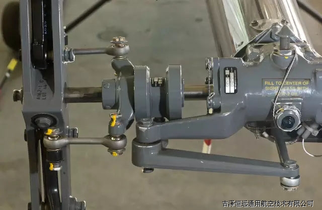
Rod Ends: Free without looseness
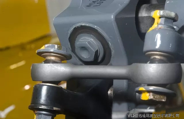
In the two pictures above, you can see how the pitch link rod end connects to the tail rotor.
On the right side, the pitch change mechanism acts as a swashplate, collectively feathering the tail rotor as commanded by the anti-torque pedals. The left edge is connected to the blade horn. You can see the spherical ball that the bolts go through, and this ball sits inside a race in the dog-bone shaped rod. Between the ball and the race is a teflon material to allow them to work freely.
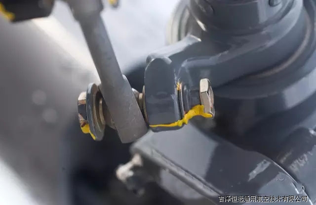
The above picture shows the end of the pitch link connected to the tail rotor swashplate. This part moves only when you move the anti-torque pedals.
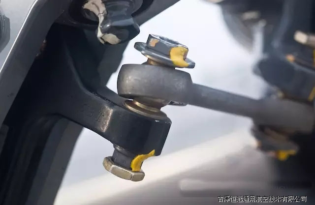
This picture shows the rod end which attaches to the tail rotor blade. The "rod" is a pitch link that transfers tail rotor pitch information from the tail rotor attachment assembly to the rotating tail rotor blades. The inner part of the rod moves when you move the anti-torque pedals. The outer part (pictured here) cycles each time the tail rotor completes one revolution (because the tail rotor flaps). Because of this, the outer rod end bearing wears out much faster than the inner bearing. When the outer bearing is reaching wear limits, the mechanic will typically flip it over, effectively doubling the life of the bearings.
Inside the rod end bearing is a teflon material which is what allows the ball and socket to smoothly move without any lubricant such as grease or oil. You may find some fine brown dust around the bearing - this is the teflon material that is wearing out. When enough teflon material wears out, the ball and socket become loose and you get excessive play in the control rod. You can check it by holding the rod and the blade horn (the black section in the photograph) and wiggling the two parts. As the bearing wears out, the horn will have more play.
Pitch Link Jam Nuts: Tight
In the previous picture, you can see that a bolt goes through the center of the pitch link rod end, through the blade horn, and into a nut. The bolt end is at the top in the picture, and the nut is on the bottom. The nut is a grey material, and below it you see the jam nut which is more of a gold color. The purpose of the jam nut is to prevent the nut from loosening. You can see in the picture that there is a stripe of yellow torque stripe going from the blade pitch horn, over the nut, and then over the jam nut. This lets you know that none of those components have rotated, and therefore that the nuts are still torqued tightly.
Another name for the jam nut is a "Pal Nut'.
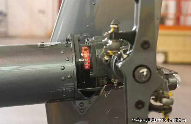
Teeter Bearings: Check condition

Teeter Bearing Bolt: Does not rotate
In the picture agove, we are looking at the nut end of the teeter bearing bolt. A nut and a pal nut are under the white torque stripe paint. Each end of the bolt goes through a bearing which allows the tail rotor to teeter (flap) around the bolt. If the bearing were to fail and seize, the entire bolt might rotate along with the tail rotor flapping. This would quickly wear out the bolt and cause a failure.
You can see a ring of black material surrounding the bolt. This is some sort of rubberized material which prevents excessive flapping during startup and shutdown. One problems with it on preflight is that it masks the wear in the teeter bearings. In earlier designs, you could see the bearing and you could judge when the bearing was getting loose. That is more difficult now.
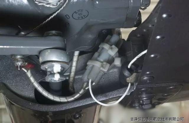
Control Bellcrank: Free without looseness
In this picture you can see the tail rotor pitch control bellcrank. When the pilot moves the pedals, the push/pull tube moves forward and back and operates the bellcrank. You should check that the bolts all have pal nuts (jam nuts) and that the torque stripe is unbroken. You should pull the bellcrank forward and back and listen to the noise coming from the tailcone. It is common to hear a noise that I can best describe as "wuuurp, wuurp" (this is the hanger for the push pull tube being excited) but you should not hear any metallic scraping noises.
未完待续...